Perforated cable management from 50 mm to 1200 mm width — engineered support for organised, ventilated and safe cable routing.
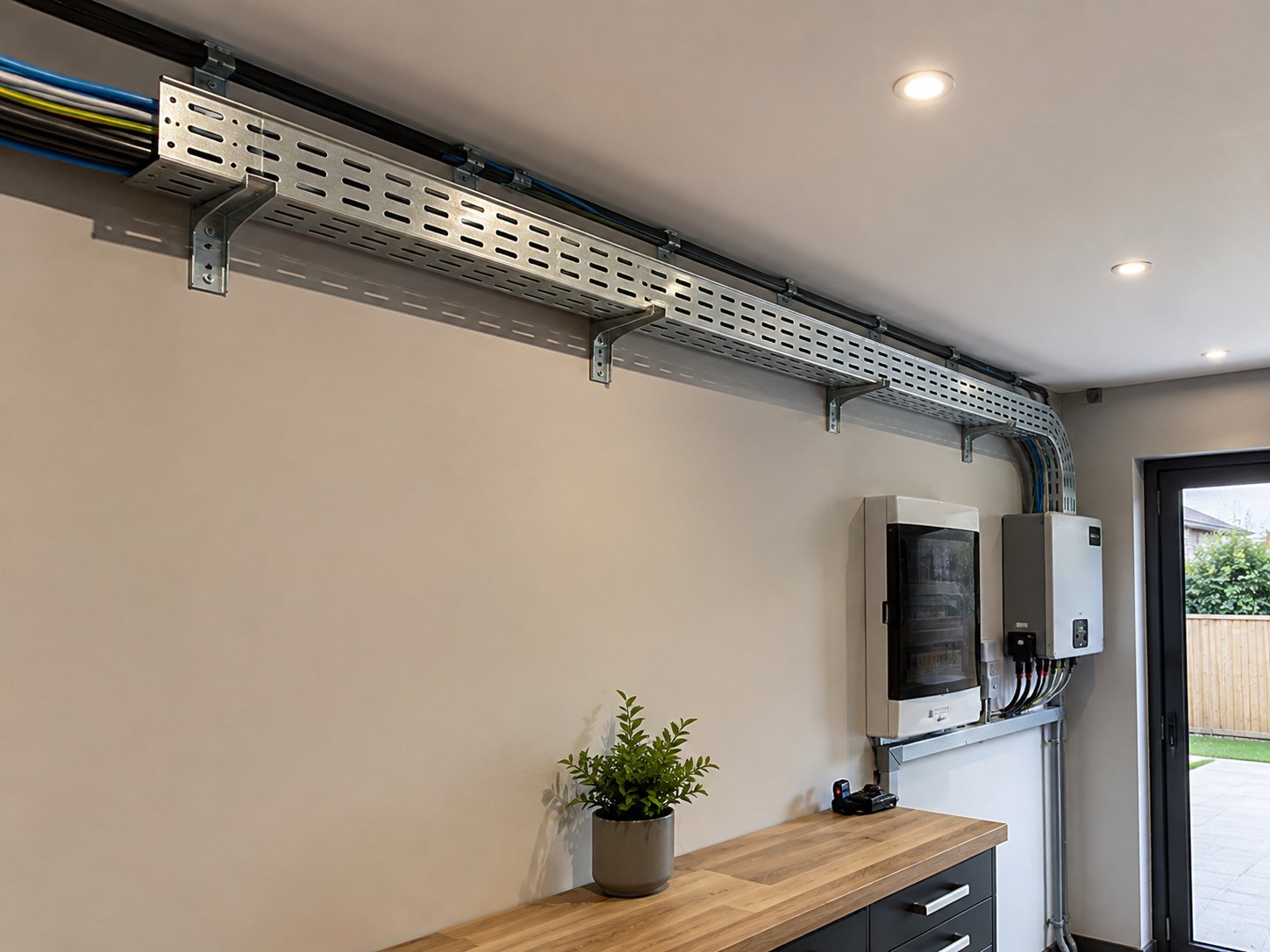
Our perforated G.I. cable trays support insulated power and control cables across industrial and commercial installations. Perforations provide ventilation and easy clamping, while formed edges add rigidity for long spans.
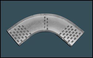
Manufactured in widths from 50 mm to 1200 mm with sheet thickness from 1.6 mm to 6 mm, in standard 2.5 m lengths — choose pre-galvanized, powder-coated or hot-dip galvanized finish to suit the environment. Bends, tees, reducers and covers are available to complete the run.
| Type | Perforated cable tray |
|---|---|
| Width Range | 50 mm to 1200 mm |
| Sheet Thickness | 1.6 mm to 6 mm |
| Standard Length | 2.5 m |
| Finishes | Pre-galvanized / powder-coated / hot-dip galvanized |
| Accessories | Bends, tees, reducers, covers, couplers |
Cable trays are usually bought as steel fabrication, but they perform as electrical infrastructure: they carry the plant's power and control wiring, determine how cables breathe and shed heat, and — properly bonded — form part of the earthing and EMC strategy of the installation.
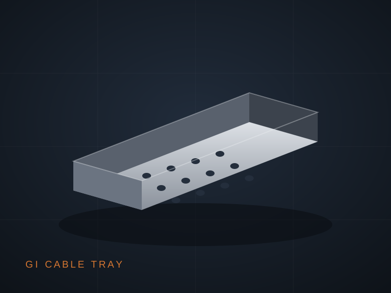
The perforated tray is the general-purpose workhorse of this family. Slotted perforations ventilate cables (raising permissible current versus enclosed raceways), provide anchor points for ties and clamps at any position, and drain washdown or condensation instead of pooling it against insulation.
Metal Hub trays are press-formed from structural sheet in widths from 50 to 1200 mm and thicknesses from 1.6 to 6 mm, with return-flanged edges that add beam stiffness and protect pulling crews from cut edges. Three finishes cover the exposure spectrum: pre-galvanized for dry interiors, hot-dip galvanized after fabrication for outdoor and coastal duty, and powder-coated where colour coding or added chemical resistance is specified.
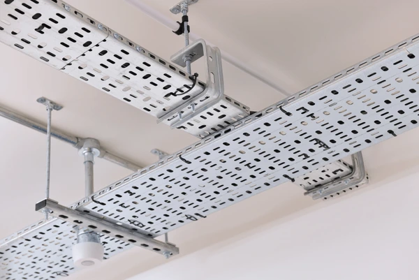
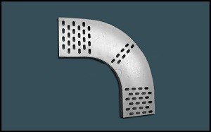
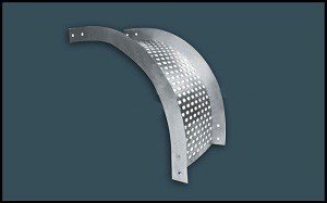
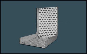
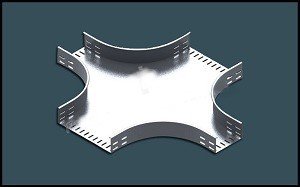
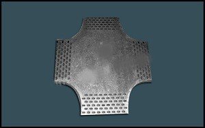
A complete accessory system — bends, tees, reducers, crosses, covers and coupler hardware — ships with the tray so routes assemble from catalogued parts rather than site improvisation, keeping bend radii cable-safe and earth continuity intact across every joint.
Good to know: Bond every tray run to earth at both ends and across each joint — a continuous tray is a ready-made parallel earth path and EMC screen for the cables it carries.
A tray is a beam: its load capacity comes from section geometry, chiefly the return flange depth and sheet thickness. That is why capacity is specified as load per span — the same tray carries more with supports at 1.5 m than at 2.5 m, and heavy cable fills call for thicker sheet or closer supports rather than hope.
Perforation geometry balances three demands: enough open area for airflow and fixing, enough remaining steel for strength, and slot patterns that accept standard ties and clamps anywhere along the run. Couplers with serrated hardware maintain electrical continuity across joints, which keeps the tray usable as a bonding conductor.
| Parameter | Range | Notes |
|---|---|---|
| Width | 50 – 1200 mm | In standard increments |
| Side height | 25 / 40 / 50 / 75 / 100 mm | Per cable fill |
| Sheet thickness | 1.6 – 6 mm | Per load and span |
| Standard length | 2.5 m | Custom lengths to order |
| Accessories | Bends, tees, crosses, reducers, covers, couplers | Catalogued system parts |
| Finish | Process | Best environment |
|---|---|---|
| Pre-galvanized (GI) | Formed from zinc-coated coil | Indoor, dry plant rooms |
| Hot-dip galvanized | Dipped after fabrication — edges sealed | Outdoor, humid, coastal, process plants |
| Powder-coated | Epoxy/polyester over pre-treated steel | Colour-coded routes, chemical areas |
Representative safe working values for perforated tray; project spans verified against fill calculation.
| Tray width / sheet | Support span 1.5 m | Support span 2.0 m |
|---|---|---|
| 300 mm / 1.6 mm | ≈ 60 kg/m | ≈ 40 kg/m |
| 450 mm / 2.0 mm | ≈ 85 kg/m | ≈ 60 kg/m |
| 600 mm / 2.5 mm | ≈ 110 kg/m | ≈ 80 kg/m |
| 900 mm / 3.0 mm | ≈ 140 kg/m | ≈ 100 kg/m |
| Parameter | Perforated tray | Ladder tray | Solid raceway |
|---|---|---|---|
| Cable ventilation | Good | Best | Poor |
| Small-cable support | Excellent | Needs closer rungs | Excellent |
| Dust/drip protection | Moderate (add cover) | Low | Best |
| Typical duty | Power + control mix | Heavy power feeders | Instrumentation |
| Application | Recommended tray | Finish |
|---|---|---|
| Indoor LT power + control | Perforated 300 – 600 mm | Pre-galvanized |
| Outdoor plant / rooftop runs | Perforated with covers | Hot-dip galvanized |
| Coastal or corrosive plants | Perforated, 2.5 mm+ | Hot-dip galvanized |
| Server / instrumentation routes | Perforated 50 – 150 mm | Powder-coated for identification |
| Heavy feeder corridors | Ladder type (on request) | Hot-dip galvanized |
Fix brackets or hangers at the span assumed in the load table — closer where fills are heavy or accessories concentrate load.
Join lengths with coupler plates and serrated hardware for mechanical strength and electrical continuity.
Form direction and level changes with factory bends and tees so minimum cable bend radii are preserved.
Lay cables in planned tiers, tie at regular intervals through the perforations, and respect fill and derating limits.
Bond at both ends and across expansion joints with GI strip or flexible jumpers; the tray becomes part of the protective bonding network.
Add covers on outdoor, dusty or drop-prone sections; leave ventilated sections free where heat dissipation governs.
A galvanized tray system needs little care in itself; inspection focuses on what changes around it — added cable weight, corrosion at site-cut edges, and loosened joints from vibration. An annual walkdown catches all three cheaply.
In corrosive plants, watch the hardware before the tray: bolts and couplers are the thinnest zinc in the system and signal environmental attack first. Replacing hardware early is trivial; replacing a corroded run is not.
Pre-galvanized for dry interiors; hot-dip galvanized wherever weather, humidity or chemistry is involved — the post-fabrication dip seals cut edges and welds; powder-coated where colour identification or specific chemical resistance is required.
Load per span. Take the planned cable weight per metre, choose your support span, and read the table — heavier fills need thicker sheet or closer supports. We verify project cases free of charge.
Yes. Bond each run at both ends and across joints. A bonded tray is a protective conductor and EMC screen; an unbonded tray can rise to dangerous potential during a cable fault.
Yes — the full accessory system (bends, tees, crosses, reducers, covers, couplers) ships from the same line, in the same finish, so routes assemble without site fabrication.
50 mm to 1200 mm as standard, in side heights from 25 to 100 mm and thicknesses 1.6 to 6 mm, in 2.5 m lengths or custom lengths against order.
Mixed power-and-control fills with small cables favour perforated; very heavy feeder corridors favour ladder for ventilation and weight. Many plants use both — we supply either against the same specification sheet.
Share sizes and quantities — we'll quote the same working day.