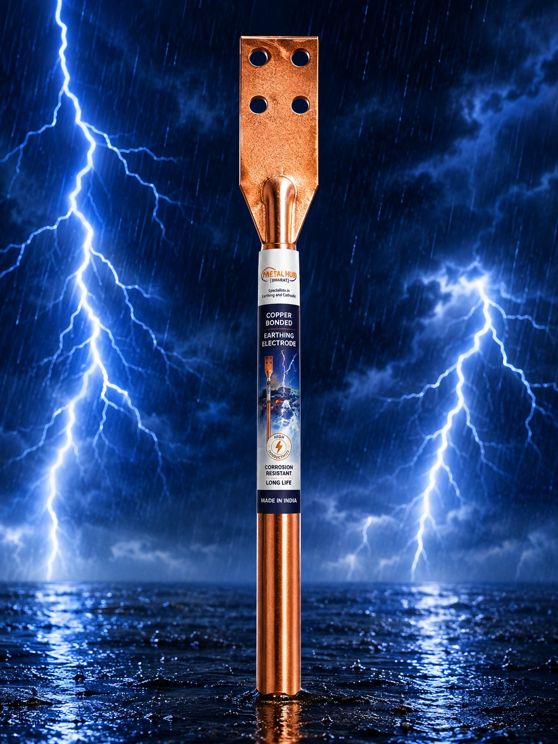
Early Streamer Emission protection tested to NFC 17-102 — paired with certified digital strike counters so you always know your system is working.
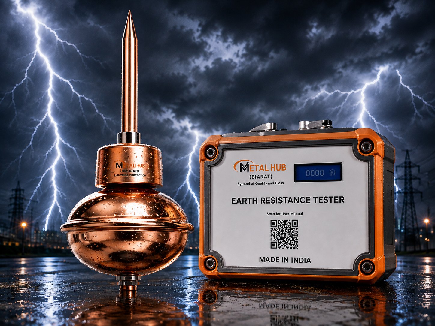
Our ESE (Early Streamer Emission) lightning arresters launch an upward leader earlier than conventional rods, extending the protection radius over the entire structure and its surroundings. Each arrester is tested to the French NFC 17-102 standard — the internationally recognised benchmark for ESE terminals.
The companion digital lightning strike counter is certified at 100kA (8/20µs impulse), features a 6-digit display and an IP67-rated enclosure — recording every discharge so maintenance teams can verify system activity at a glance.
| Type | Early Streamer Emission (ESE) air terminal |
|---|---|
| Standard | Tested to NFC 17-102 |
| Material | Stainless steel |
| Protection Radius | As per NFC 17-102 protection level and ΔT of model |
| Strike Counter | 6-digit digital, certified 100kA (8/20µs), IP67 |
| Mounting | On elevation mast above highest point of structure |
A lightning strike does not simply fall from the cloud to the ground. As the stepped leader descends, grounded objects launch upward streamers toward it; the first streamer to connect defines the strike point. Conventional Franklin rods wait passively for this moment. An ESE (Early Streamer Emission) terminal actively conditions the local field and launches its upward streamer earlier — by a characterised time advantage called ΔT.
That early start translates into geometry: the ESE terminal's streamer travels further before any competing streamer connects, effectively enlarging the protected volume. This is why a single ESE terminal on a mast can protect a radius that would require an extensive mesh of conventional rods and conductors — a decisive advantage on large roofs, open yards, solar plants and heritage structures where surface conductors are unwelcome.
The governing standard is NFC 17-102, which defines the ΔT test method, protection radius calculation, protection levels I–IV, and installation requirements. Metal Hub ESE terminals are tested to NFC 17-102; equally important, every installation we supply is designed as a complete chain — terminal, mast, down conductor, test joint, strike counter and dedicated earth pit — because a lightning system is only as good as its weakest series element.
The IP67-rated digital strike counter completes the engineering loop. Certified at 100kA (8/20µs), it registers every discharge that passes to earth, giving maintenance teams objective evidence of system activity and a trigger for post-strike inspection.
Good to know: An ESE terminal without a verified low-resistance earth pit is decoration. Specify the earth termination (≤ 10 ohm, ideally lower) in the same purchase order as the arrester.
The protection radius Rp of an ESE terminal is a function of its height h above the surface to be protected, the selected protection level (I–IV, from the site risk assessment), and the terminal's tested ΔT advantage. Standard tables derived from NFC 17-102 give Rp directly — the values below are representative for a typical tested terminal.
Captured current flows through a dedicated down conductor — routed outside occupied areas, with bends kept gentle to avoid flashover — through a test joint that allows the earth to be measured in isolation, and into an earth termination that disperses the charge. The strike counter sits in this path and increments on each discharge.
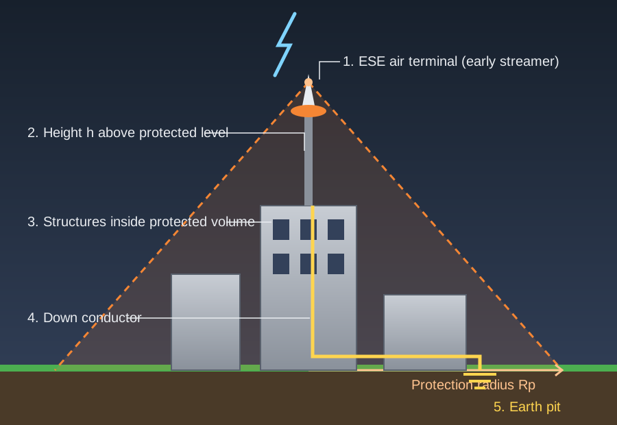
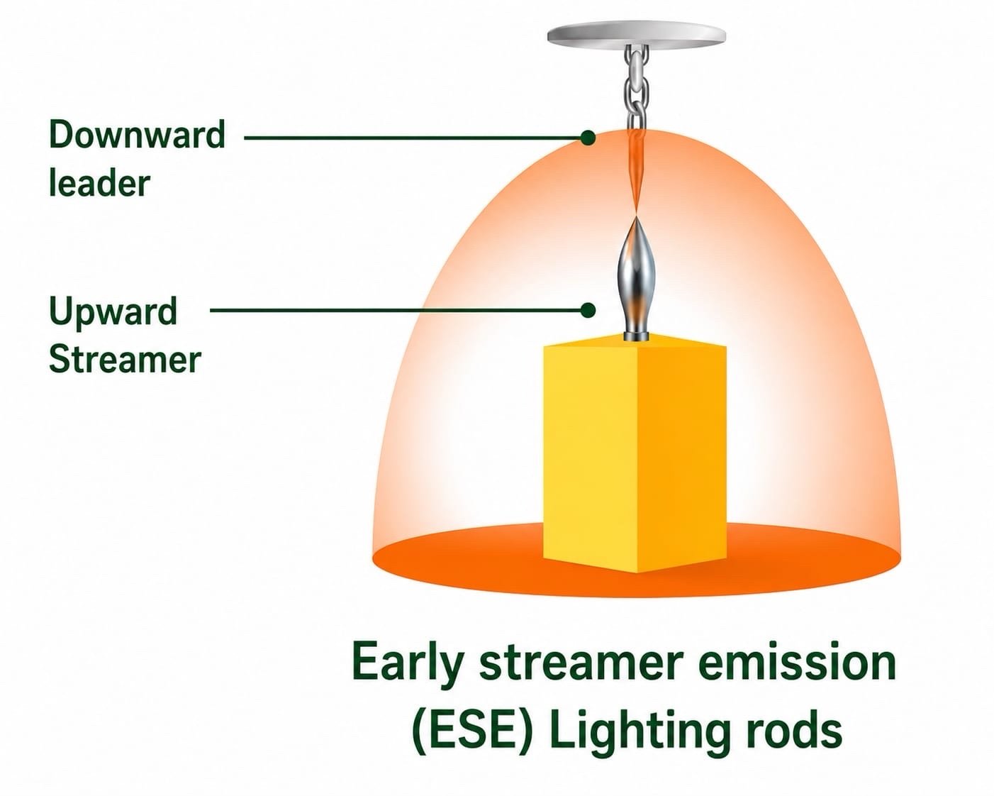
Representative values for a terminal at height h above the protected level; the site-specific figure comes from the NFC 17-102 calculation for the selected model and protection level.
| Height h | Level I (highest security) | Level II | Level III | Level IV |
|---|---|---|---|---|
| 2 m | ≈ 15 m | ≈ 17 m | ≈ 19 m | ≈ 21 m |
| 4 m | ≈ 30 m | ≈ 34 m | ≈ 38 m | ≈ 42 m |
| 6 m | ≈ 45 m | ≈ 51 m | ≈ 57 m | ≈ 63 m |
| 10 m+ | ≈ 55 m | ≈ 65 m | ≈ 75 m | ≈ 85 m |
| Parameter | Value | Notes |
|---|---|---|
| Certification impulse | 100 kA (8/20 µs) | Independently certified |
| Display | 6-digit electromechanical/digital | Non-resettable count integrity |
| Ingress protection | IP67 | Permanent outdoor mounting |
| Sensing | In-line on down conductor | Registers every discharge to earth |
| Power | Self-powered by discharge | No external supply required |
The arrester is one element of a series chain; each element has its own requirement.
| Component | Requirement | Purpose |
|---|---|---|
| Air terminal | NFC 17-102 tested, stainless steel | Defines the protected volume |
| Elevation mast | ≥ 2 m above highest point | Radius grows with height h |
| Down conductor | 70 mm² Cu (or equivalent), shortest route | Carries impulse current safely |
| Test joint | Accessible disconnect link | Isolated earth measurement |
| Strike counter | 100 kA certified, IP67 | Event recording |
| Earth termination | ≤ 10 ohm dedicated pit(s) | Final dissipation |
| Standard | Title / scope | Relevance |
|---|---|---|
| NFC 17-102 | ESE lightning protection systems | Terminal testing, radius calculation, installation |
| IEC 62305 | Protection against lightning | Risk assessment and protection levels |
| IS 2309 | Protection of buildings against lightning | Indian code for LPS practice |
| IEC 62561 | LPS components | Conductors, joints, test links |
Level comes from the IEC 62305 risk assessment; as a first orientation:
| Site type | Typical level | Rationale |
|---|---|---|
| Explosive/fuel storage, hospitals | Level I | Maximum security, smallest permitted radius |
| Schools, high-occupancy buildings, data centres | Level II | High consequence of failure |
| Industrial plants, warehouses | Level III | Standard industrial risk |
| Open yards, low-occupancy structures | Level IV | Lower consequence, larger radius allowed |
| Parameter | ESE system | Conventional system |
|---|---|---|
| Coverage per terminal | Large radius from one mast | Local zone per rod; mesh for area |
| Roof intrusion | Minimal — single mast | Extensive conductors across roof |
| Aesthetics / heritage suitability | Excellent | Poor to moderate |
| Installed cost for large areas | Usually lower | Rises with area |
| Standard basis | NFC 17-102 | IEC 62305-3 / IS 2309 |
Determine the required protection level (I–IV) per IEC 62305 from structure type, occupancy and exposure, then select terminal model and mast height so the calculated radius covers every corner of the structure.
Fix the mast so the terminal tip stands at least 2 m above the highest point within the protected zone, with guying or brackets rated for site wind loads.
Run the shortest, straightest path to ground level along the external face; keep bend radii generous and avoid loops, sharp re-entries and proximity to service cables.
Install the strike counter in-line at an inspectable height (typically ~2 m above grade) and a test disconnect link below it.
Terminate in a copper bonded or pure copper electrode pit with conductive backfill, achieving ≤ 10 ohm — lower where soil permits. Bond to the main earthing system per code.
Measure the earth in isolation via the test joint, record counter reading, photograph the installation and issue the commissioning record.
Lightning systems live outdoors in the worst weather on the site, so scheduled inspection is part of the design. The strike counter turns maintenance from guesswork into evidence: any increment since the last reading triggers the post-strike checklist.
Annual verification covers mechanical integrity (mast, fasteners, conductor fixing), electrical continuity of the down conductor, and the isolated earth resistance via the test joint — trended year over year exactly like any earth pit.
A conventional rod waits for the strike; an ESE terminal launches its upward streamer earlier (the tested ΔT advantage), connecting with the downward leader sooner and therefore protecting a much larger radius from a single point.
It depends on terminal model, its height above the protected level and the required protection level. As orientation, a typical tested terminal 6 m above a roof protects roughly 45–63 m radius depending on level; we compute the exact NFC 17-102 figure for your site free of charge.
ESE systems are specified widely in India on the basis of NFC 17-102 testing, alongside IS/IEC-based conventional systems. Many consultants specify ESE for large roofs, tanks, solar plants and heritage buildings; we supply compliance documentation for approval files.
Because without it you cannot know the system has operated. The counter provides maintenance triggers, insurance evidence and client assurance — and ours is certified to register discharges up to 100 kA with IP67 sealing.
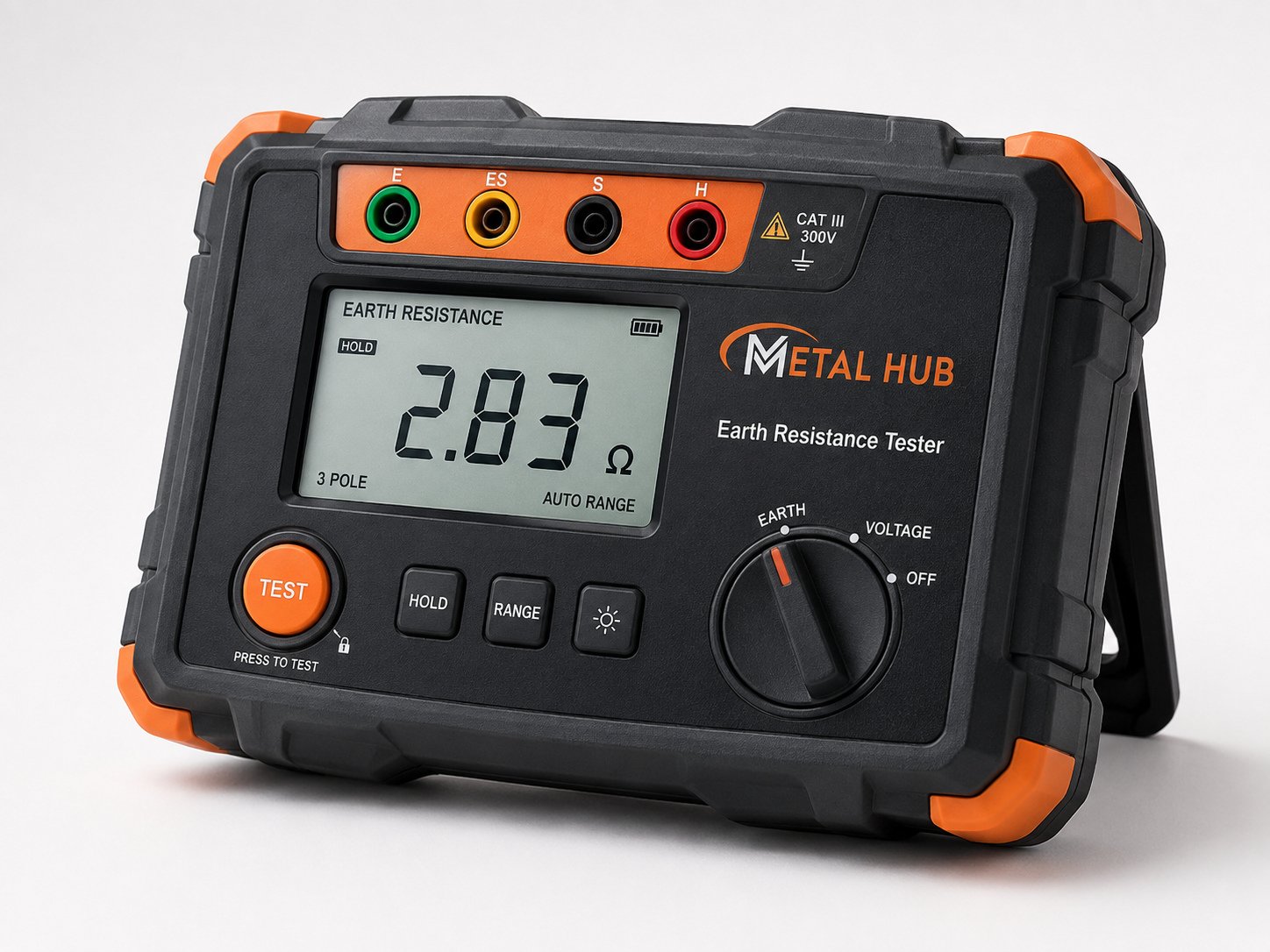
NFC 17-102 practice targets 10 ohm or better for the dedicated earth termination. In high-resistivity soil this is achieved with multiple electrodes and conductive backfill rather than a single deeper rod.
Yes, if all of them fall inside the calculated protection radius at the required level — a common and economical arrangement for factory complexes and institutional campuses.
Share sizes and quantities — we'll quote the same working day.