Lab-proven grounding backbone — steel-core electrodes with molecularly bonded copper for decades of low, stable earth resistance.
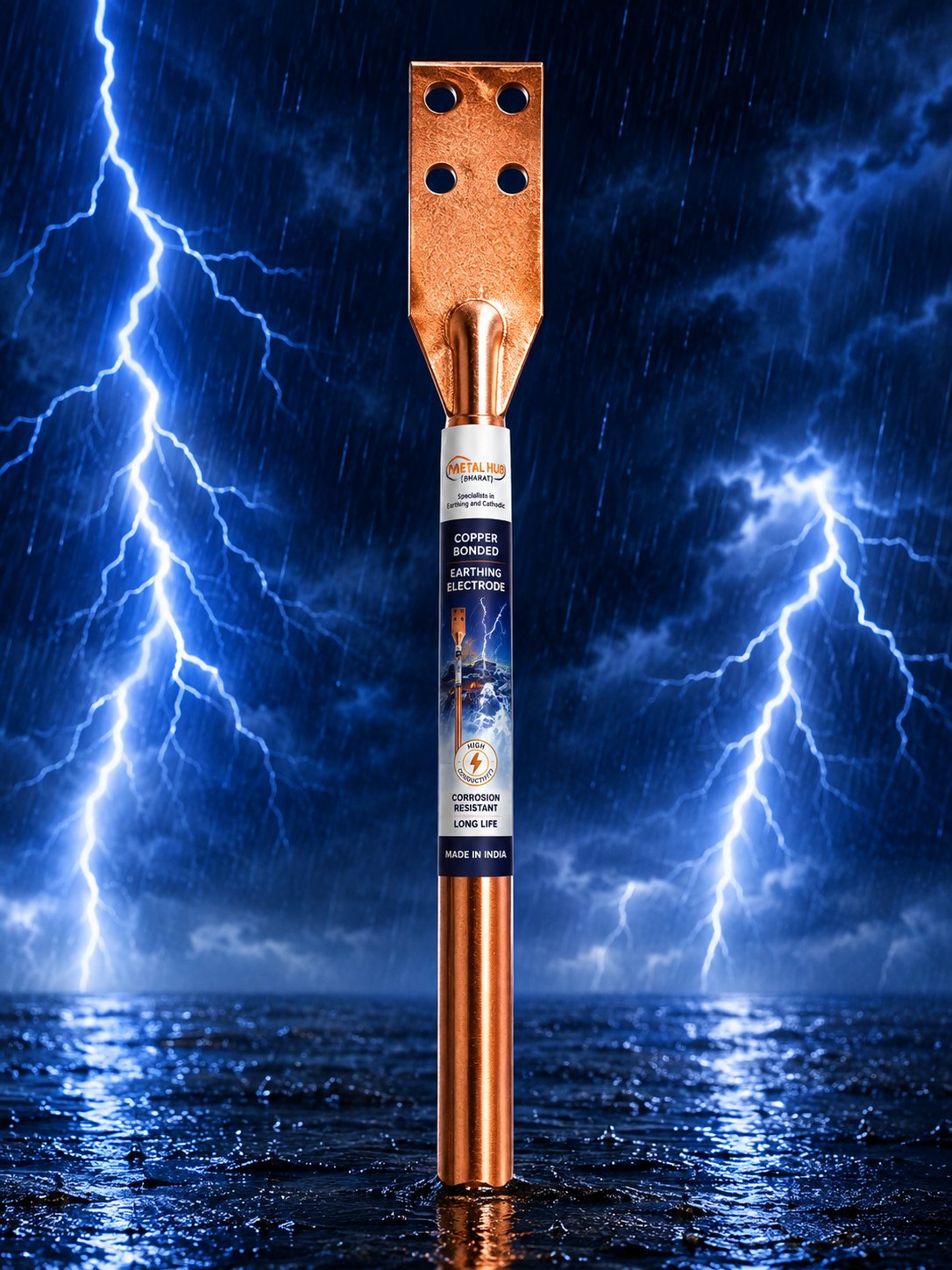
Our copper bonded earthing electrodes combine a high-tensile steel core with a uniformly bonded copper coating. The molecular bonding process ensures the copper never peels, cracks or separates — even when driven into hard soil — giving the electrode both mechanical strength and excellent conductivity.
Every batch is independently tested at NABL-accredited and CPRI laboratories, and the crystalline-enhanced construction retains soil moisture around the electrode for consistently low resistance without maintenance.
| Construction | High-tensile steel core with molecularly bonded electrolytic copper coating |
|---|---|
| Standard Diameters | 14.2 mm, 17.2 mm, 25 mm (custom sizes on request) |
| Standard Lengths | 1 m, 2 m, 3 m |
| Copper Coating | 100 / 250 micron options |
| Testing | NABL-accredited & CPRI laboratory tested |
| Maintenance | Maintenance-free; pairs with graphite backfill compound |
| Suitable Soil pH | 5.0 – 8.0 |
Every earthing electrode fights the same two enemies for its entire service life: soil corrosion and mechanical stress. Bare mild steel corrodes quickly in most Indian soils; solid copper resists corrosion superbly but is soft, expensive and attractive to theft. The copper bonded electrode resolves this trade-off by metallurgically depositing a continuous layer of 99.9% electrolytic copper onto a high-tensile steel core, giving the strength of steel on the inside and the corrosion chemistry of copper at the soil interface.
The word bonded matters. In electro-deposition bonding, copper is grown molecule by molecule onto the prepared steel surface, so there is no discrete boundary that can delaminate. Cheaper alternatives — copper cladding wrapped under pressure, thin flash plating, or copper paint — routinely fail at the moment of installation: when the rod is driven into compacted soil, a mechanically attached skin scrapes back and exposes bare steel, which then becomes the anode of a corrosion cell and is consumed first.
A correctly specified copper bonded electrode with 250 micron coating is generally accepted to deliver 30+ years of service in normal soils. That is why utilities, data centres and process industries worldwide specify copper bonded rods as the default electrode for both power-frequency fault earthing and lightning protection terminations.
Metal Hub electrodes are manufactured on a controlled electro-plating line, verified for coating thickness and adhesion, and independently tested at NABL-accredited and CPRI laboratories. Each supply can be accompanied by test documentation for project QA files.
Good to know: Coating thickness is the single biggest driver of electrode life. 100 micron suits budget commercial work; specify 250 micron wherever design life beyond 20 years or corrosive soil is involved.
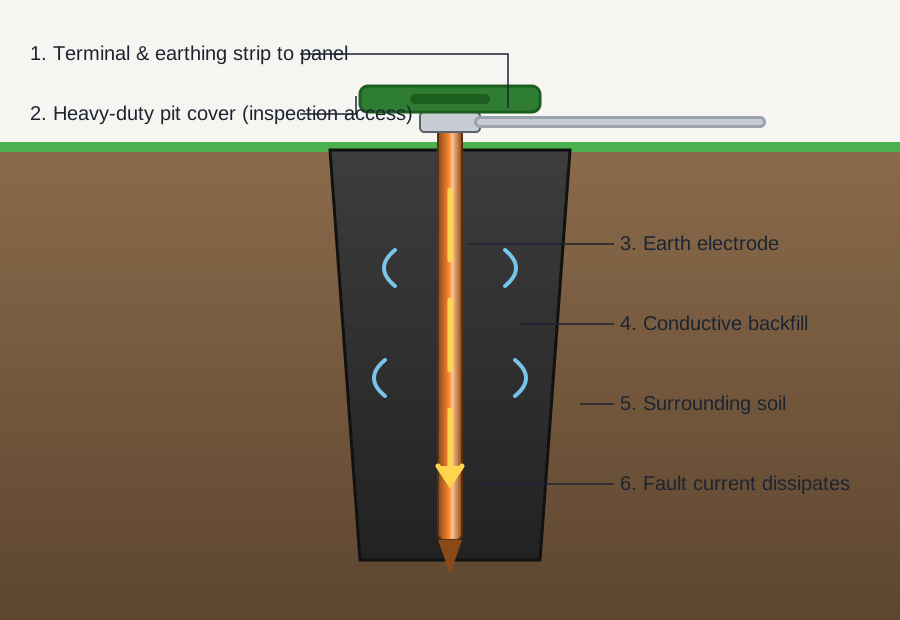
During a fault or lightning discharge, current enters the electrode from the terminal at the top and must transfer into the surrounding soil across the electrode's surface area. Resistance to that transfer is dominated by the first few centimetres of soil around the rod — which is exactly where conductive backfill compound is placed. The compound forms a permanently moist, low-resistivity cylinder that effectively enlarges the electrode's diameter.
The deeper the electrode, the more it engages stable, moist soil layers that do not dry out in summer. This is why a single 3 m electrode usually outperforms two 1.5 m electrodes placed close together, and why the electrode tip is forged to a point — allowing it to be driven to full depth without pre-boring in most soils.
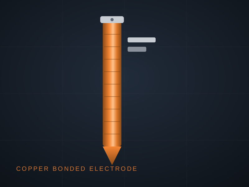
Custom lengths and diameters can be manufactured against project requirement.
| Nominal diameter | Length | Copper coating | Typical application |
|---|---|---|---|
| 14.2 mm | 1 m / 2 m / 3 m | 100 / 250 micron | Residential and small commercial earthing |
| 17.2 mm | 2 m / 3 m | 100 / 250 micron | Commercial buildings, panels, lifts, DG sets |
| 20 mm | 3 m | 250 micron | Industrial plants, HT installations |
| 25 mm | 3 m | 250 micron | Substations, lightning protection terminations |
| Property | Value | Why it matters |
|---|---|---|
| Core material | High-tensile low-carbon steel | Withstands driving force without bending |
| Copper purity | 99.9% electrolytic grade | Maximum conductivity and corrosion resistance |
| Bond type | Molecular electro-deposition | Coating cannot peel or slide during driving |
| Tensile strength | ≈ 600 N/mm² | Deep driving in compacted soils |
| Coating adhesion | Passes bend/adhesion verification | Integrity retained at bends and clamp points |
| Suitable soil pH | 5.0 – 8.0 | Covers the majority of Indian soil conditions |
Metal Hub electrodes are designed to align with the requirements of the following codes of practice.
| Standard | Title / scope | Relevance to this product |
|---|---|---|
| IS 3043 | Code of practice for earthing | System design, electrode sizing, target resistance values |
| IS 2309 | Protection of buildings against lightning | Down conductors, terminations and earthing of LPS |
| IEC 62561-2 | Lightning protection system components | Requirements for conductors and earth electrodes |
| IEC 62305 | Protection against lightning (series) | Risk assessment and protection measures |
| UL 467 | Grounding and bonding equipment | North-American benchmark for electrode hardware |
Indicative values used for first-pass design; always confirm with an on-site soil resistivity test.
| Soil type | Typical resistivity (ohm-m) | Earthing difficulty |
|---|---|---|
| Wet marshy / organic soil | 5 – 40 | Easiest — lowest resistance per electrode |
| Clay / loam (moist) | 20 – 100 | Easy |
| Clay-sand mixtures | 80 – 250 | Moderate |
| Sand / gravel (moist) | 250 – 500 | Hard — backfill compound recommended |
| Dry sand / murram | 500 – 1000 | Very hard — multiple electrodes + compound |
| Rock / hard strata | 1000+ | Requires engineered multi-electrode design |
How the three Metal Hub electrode families compare on the parameters buyers ask about most.
| Parameter | Copper bonded | Pure copper | GI pipe |
|---|---|---|---|
| Conductivity at soil interface | Excellent | Excellent | Good |
| Mechanical driving strength | Excellent (steel core) | Moderate | Good |
| Corrosion life (typical soil) | 30+ years | 40+ years | 10 – 15 years |
| Theft attractiveness | Low | High | Low |
| Relative cost | Medium | High | Low |
| Best fit | Default for most projects | Critical / HV installations | Budget & light-duty earthing |
Contract specifications always prevail; these are widely used design targets.
| Installation type | Typical target | Usual electrode arrangement |
|---|---|---|
| Large power station | ≤ 0.5 ohm | Grid + multiple deep electrodes |
| EHT / major substation | ≤ 1 ohm | Earth grid with electrode array |
| 33 kV substation | ≤ 2 ohm | Multiple 3 m electrodes in parallel |
| Industrial plant / DG | ≤ 5 ohm | 2 – 4 electrodes with compound |
| Commercial building / lift / panel | ≤ 5 ohm | 1 – 2 electrodes with compound |
| Residential | ≤ 8 ohm | Single 2 – 3 m electrode |
Choose a location at least 1.5 m from the foundation, away from water drainage and other services, and ideally in naturally moist ground. Maintain at least one electrode-length spacing from any other earth electrode.
Auger a 100 – 150 mm bore (or excavate a 300 mm pit) to the electrode length. In soft soil the pointed electrode may be driven directly with a driving head.
Lower or drive the electrode centrally so the terminal sits roughly 150 mm below finished ground level, leaving room for the connection and cover.
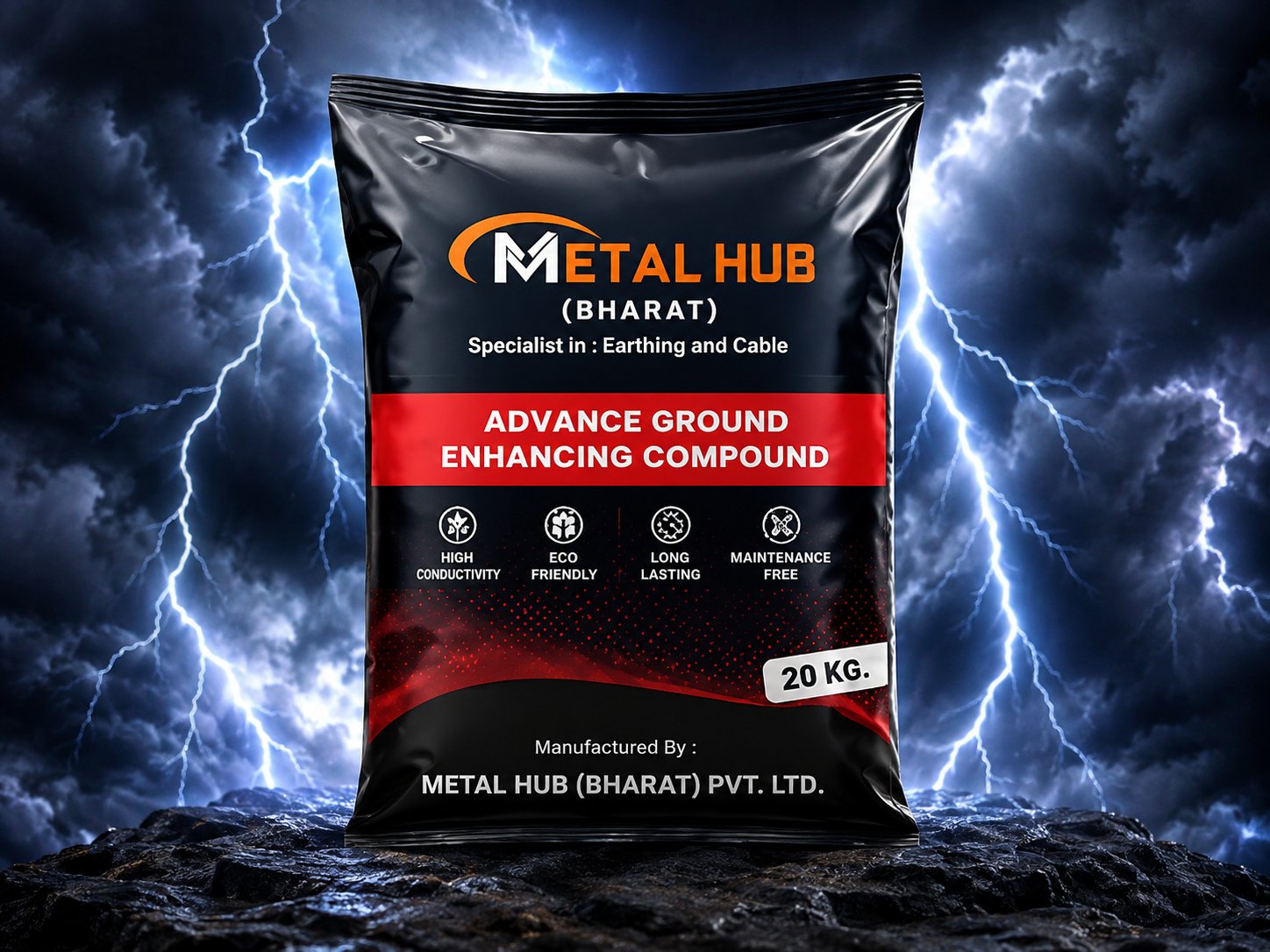
Mix Metal Hub ground-enhancing compound to a slurry and pour around the electrode in stages, rodding to remove air pockets, until the annulus is filled to near ground level.
Connect the GI or copper strip using the supplied clamp or by exothermic welding. Apply anti-corrosion protection over the finished joint.
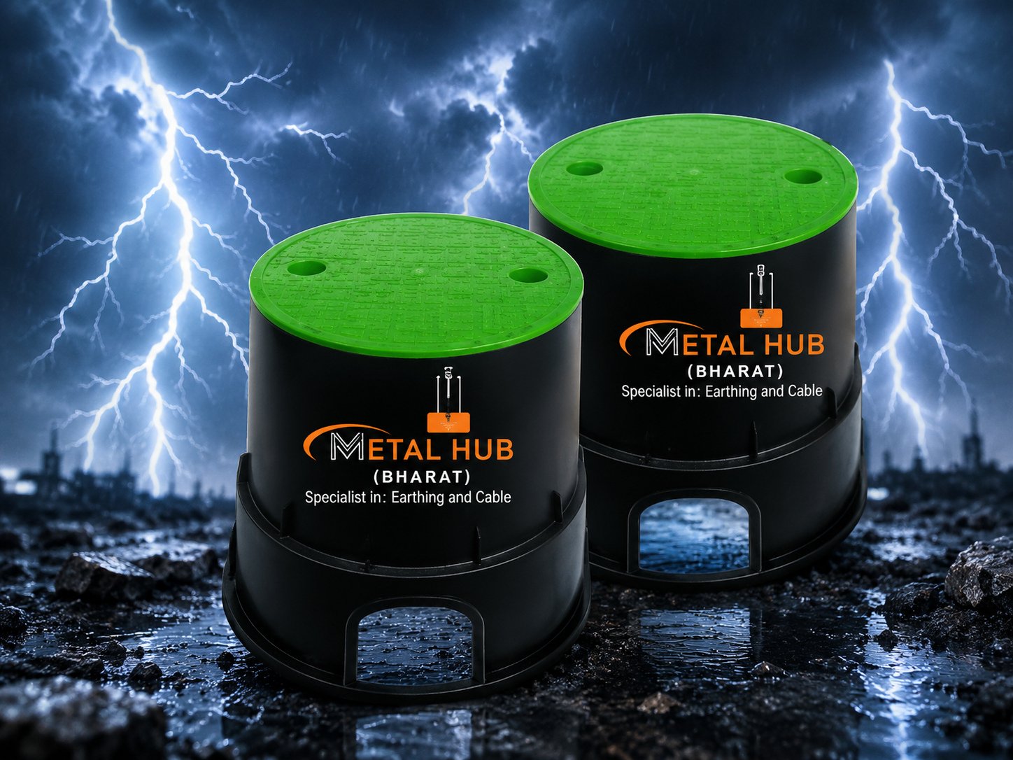
Install the FRP pit cover flush with finished level so the terminal remains accessible for future testing.
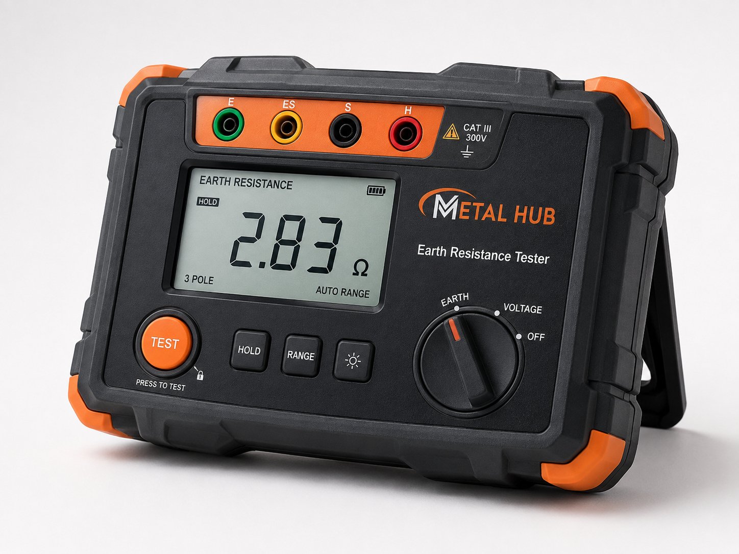
Measure earth resistance with a fall-of-potential test after 48 hours of soil settlement. Record the value, date and pit location as the baseline for annual comparison.
A correctly installed copper bonded pit is maintenance-free in the true sense: no watering, no recharging, no periodic excavation. What remains essential is periodic verification — an earthing system can be degraded by later construction work, soil disturbance, or a stolen strip, and the only way to know is to measure.
Best practice is an annual earth resistance test, performed in the driest month so you record the worst-case value. A rising trend across years signals a drying pit surround or a deteriorating joint and should be investigated before the value crosses the design target.
With 250 micron coating in soil of pH 5 – 8, a service life of 30 years or more is the accepted industry expectation. The NABL/CPRI-tested coating on Metal Hub electrodes is uniform along the full length, including the threaded sections, which is where inferior rods usually fail first.
Cladding mechanically wraps a copper sheet around steel, leaving a boundary that can slide or tear open when the rod is driven. Bonding electro-deposits copper directly onto the steel at the molecular level, so the layer behaves as one material with the core and survives driving intact.
Choose 250 micron for industrial plants, substations, lightning protection and any project with a design life above 20 years or aggressive soil. 100 micron is acceptable for light commercial and residential earthing with shorter design horizons.
Full electrode length — typically 3 m for commercial and industrial work. Depth matters more than quantity: deeper rods reach permanently moist strata, keeping resistance stable through summer.
Start from the measured soil resistivity. In good soil a single 3 m electrode with compound often achieves 2 – 5 ohm; harder targets are met by adding electrodes in parallel, spaced at least one electrode-length apart, until the combined value meets the design figure.
No. The combination of a deep electrode and hygroscopic backfill compound retains soil moisture around the rod, which is what made traditional salt-and-charcoal watering pits obsolete.
Share sizes and quantities — we'll quote the same working day.